CBSE Sample Paper 2017 Physics Solution: Hello dear students, Are you looking for CBSE Sample Question Paper 2017 Physics Part Solution, If Yes then this links provide you with the expert crafted physics sample question paper 2017 along with the solutions. Not only this, we have made sure to provide you with the video explanations that go hand in hand with the questions provided below.
Ensuring that you gain the best marks is our ultimate goal. You deserve the best of solutions for every physics problem. That why is, we have provided you with the links below which include the expert crafted physics sample question paper 2017 along with the solutions. Not only this, we have made sure to provide you with the video explanations that go hand in hand with the questions provided below.
These physics sample question papers 2017 include the video solutions which are made by the best of our educators.
You can completely rely on our physics solutions for your studies.
CBSE Sample Paper 2017 Class 10 Physics Solution
|
Board |
CBSE |
|
Topic |
Sample Paper Solution |
|
Year |
2017 – 18 |
| Subject |
Physics |
| Class |
10 (Ten Class) |
Here the Official link for CBSE Sample Paper 2017 – 18
| CBSE Sample Paper 2017 – 18 | Click Here |
Solution of sample question paper 2017 – 2018
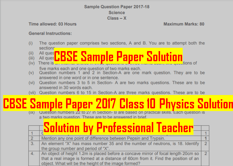
Q.4) An object of height 1.2m is placed before a concave mirror of focal length 20cm so that a real image is formed at a distance of 60 cm from it. Find the position of an object. What will be the height of the image formed?
Ans: Data
h1=1.2 m=120 cm
f=-20 cm=-0.2 m
Since the image is real and for concave mirror, real image forms on left side
v=-60 cm= -0.6 m
u= ? cm
Using mirror formula, we have
1/f=1/v+1/u
∴1/u=1/(-20)-1/(-60)
∴1/u=1/(-20)+1/60
∴1/u=1/60-3/60=(-2)/60=(-1)/30
∴ u = -30 cm
The position of object should be 30 cm from the pole of the mirror.
Now to find the height of the image we have the formula,
h2/h1 = v/u
∴h2= h1 × v/u
∴h2 = 120 × 60/30 = 120 × 2 = 240 cm
The height of image is 2.4 m.
Q.5) Why is there a need to harness non-conventional sources of energy? Give two main reasons.
Ans: We need to harness non-conventional sources of energy following for reasons,
- Conventional sources like fossil have very limited amount of stock availability, as time goes the quantity of fossil fuel, crude oil and other resources will goes on decrease and finally will come to an end.
- Conventional sources are responsible for some side effects like pollution, deforestation etc. Globally the impact of the gases emitted by burning of fossil fuel causes issues like green house effect which leads to global warming.
- Hence non-conventional sources of energy which are free from any pollution, almost free (except the cost of installation) are the most suitable and reliable alternatives for the conventional energy source.
Q.6) Name the electric device that converts mechanical energy into electrical energy. Draw the labelled diagram and explain the principle involved in this device.
Ans: The device which converts mechanical energy into electrical energy is known as electric generator.
The following diagram shows the different parts used for construction of electric motor.

Principle of working:
It works on principle of electromagnetic such that the coil rotated in uniform magnetic field, induces current in it. According to Faraday’s law of electromagnetic induction, whenever there in change in magnetic field linked with coil, current is induced in the coil. Using this phenomena an armature is rotated mechanically in strong U shaped magnet, and due to electromagnetic induction mechanical energy is converted into electrical energy.
OR
Q.6) i) What is the function of earth wire in electrical instruments?
Ans: The electrical instruments have earth wire because if there is short circuiting, overloading or any kind of leakage of current in takes place in such instruments, the excess current which generated can heat wires so as to increase its temperatures which can either damage the instrument or can cause the fire. To prevent this one terminal is always grounded or earthed.
ii) Explain what is short circuiting an electric supply.
Ans: If an insulation over the live wire and neutral wire removed by any means like, scratching of wire with rough wall, or rubbing between two doors the live wire and neutral wire gets connected which carries large amount of uncontrolled current. This produces sparking and heat in the wire termed as short circuiting. Short circuiting in the wires is very dangerous as it can catch the fire too.
iii) What is the usual current rating of the fuse wire in the line to feed (a) Lights and fans? (b) Appliances of 2kW or more power?
Ans: a) lights and fans are work on voltage of 110 V- 220 V supply has power rating of up to 1000 watt, hence for the lights and fans current rating is from 0 A- 5 A
b) Appliances of 2kW or more power uses 240 V domestic AC supply, for such instruments current rating is about 15 A.
Q.7) Draw a circuit diagram of an electric circuit containing a cell, a key , an ammeter , a resistor of 4Ω in series with a combination of two resistors (8Ω each) in parallel and a voltmeter across parallel combination. Each of them dissipate maximum energy and can withstand a maximum power of 16W without melting. Find the maximum current that can flow through the three resistors.
Ans: Following is the circuit diagram shown for the given configuration

To find current through the circuit first we need to calculate the total resistance of circuit.
R_1=4 Ω
R_2=8 Ω
R_3=8 Ω
As we can see from figure that R2 and R3 are connected in parallel, so lets find the equivalent resistance as
1/RP =1/R1 +1/R2 =1/8+1/8=2/8
∴RP=4 Ω
Now RP is connected in series with R1 hence total resistance R of circuit is then given as,
R=R1+RP
∴R=4+4=8 Ω
Effective resistance of circuit is 8 Ω.
The maximum power dissipated is given as, P= 16 W
Then by formula for Power we have,
P=VI…………(1)
But by Ohm’s law V=IR……………(2)
Then equation (1) can be
P=IR.I
∴I2 = P/R
∴I2 = 16/4
∴I2 = 4
∴I = 4 A
The maximum current that can flow through the given resistors is 4A.
Q.12) Rohit focused the image of a candle flame on a white screen using a convex lens. He noted down the position of the candle, screen and lens as under:
Position of candle = 26.0 cm
Position of convex lens = 50.0 cm
Position of screen = 74.0 cm
What is the focal length of the convex lens?
Where will the image be formed if he shifts the candle towards the lens at a position of 38 cm?
Draw a ray diagram to show the formation of the image in case (ii) as said above.
Ans: The lens used by Rohit is convex with the following measurements
Position of candle = 26.0 cm
Position of convex lens = 50.0 cm
Position of screen = 74.0 cm
Now from this we can have,
object distance ,u=26.0-50.0 cm= -24.0 cm
image distance ,u=74.0-50.0 cm=+ 24.0 cm
Focal length of lens can be found by Lens formula
1/f=1/v-1/u
∴1/f=1/24-1/(-24)
∴1/f=1/24+1/24=2/24
∴1/f=1/15
∴f=12 cm
The focal length of lens used by Rohit is 12 cm
Now Rohit shifted candle towards the lens at position of 38 cm, then
object distance, u’=38.0-50.0 cm= -12.0 cm
To find the position of image by lens formula again
1/f=1/v-1/u
∴1/v’=1/f+1/u
∴1/v’=1/12+1/(-12)
∴1/v’=1/12-1/12=1/0= ∞
The image will form at infinite distance from the lens.
Ray diagram showing the condition in (ii) is shown below.

Q.16) With the help of a labelled circuit diagram wire describe an activity to illustrate the pattern of the magnetic field lines around a straight current carrying long conducting wire . i) Name the rule that is used to find the direction of magnetic field associated with a current carrying conductor. ii) Is there a similar magnetic field produced around a thin beam of moving (a) alpha particles and (b) neutrons? Justify your answer
Ans: To understand the magnetic lines of forces produced around the straight conductor carrying conductor let’s perform the following activity.
Apparatus required: a copper wire, iron filings (or iron nails), cardboard paper, battery, plug key, table etc.
- 1) Keep white cardboard on a plane table with a small hole marked on it and pour some iron filings on it
- 2) Insert the copper wire of suitable thickness through the hole and complete the circuit as shown below.

- Now close the key so as to flow the current I in the circuit in upward direction as shown in figure.
- Observe the path traced by iron filings on the cardboard paper.
- Iron filings are arranged in the form of concentric circles as shown in fig. which explains the nature of magnetic line of forces around a straight conductor carrying current
- Right hand thumb rule is used for tracing the direction of magnetic lines of forces produced around conductor when current flows through it.
a) Alpha particles: We know that alpha particles are charged particles. It is positively charged. When sharp and thin beam of alpha particles is moves a electric/magnetic field can be produced and will similar to that of straight conductor carrying conductor.
b) Neutrons: Neutrons are charge less, so that they aren’t affected by any kind of electric or magnetic field, hence moving beam of neutrons will not show any kind of magnetism.
Q.19) Noopur needs a lens of power -4.5D for correction of her vision. a) What kind of defect in vision is she suffering from? b) What is the focal length and nature of the corrective lens? c) Draw ray diagrams showing the (a) defected eye and (b) correction for this defect. d) What are the causes of this defect?
Ans: The power of lens prescribed to Noopur is -4.5 D hence it is concave lens.
- Noopur must be suffering from the defect known as Myopia or farsightedness, in which she is able to see the nearby objects clearly but not able to see objects kept at long distance.
- Power of corrective lens is -4.5 D Hence the focal length can be found as,
∴ f=1/P
∴ f=1/(-4.5 )= – 0.22 m
Focal length of corrective lens is -0.22 m.
- The following diagram shows the defect eye due to myopia and correction made with the help of lens. Fig. 1) shows the eye with myopia and Fig.2) shows the correction in myopia with the help of concave lens.

- Myopia is mainly caused due to improper working of ciliary muscles. If we are using mobiles for long time, spending long time on screen or watching movies from short distance, the ciliary muscles pulls the eye lens so as to make is more curve and bulgy for long time and doesn’t relaxed. This decreases the focal length of eye lens, eyeball gets slightly elongated so that the image forms in front of retina instead of forming on retina. Impact of all of these factors makes the person unable to see distinct object and suffer with the defect of myopia.
Q.26) The values of current I flowing in a given resistor for the corresponding values of potential difference V across the resistor are given below:
|
I(A) |
V(V) |
| 0.5 | 1.6 |
| 1 | 3.4 |
| 2 | 6.7 |
| 3 | 10 |
| 4 | 13.2 |
Plot a graph between V and I and calculate the resistance of the resistor.
Ans: The graph between current I and potential difference V is shown as below,

The nature of graph is straight line, which indicates that Ohm’s law is obeyed.
Two find the resistance, consider any two points P and Q with co-ordinates of
P(x1,y1 ) = (1, 3.4) and Q(x2,y2 )= (3, 10),
then resistance of resistance can be obtained by finding slope of line PQ,
Slope of line PQ= (y2-y1)/(x2-x1)
Slope of line PQ= (10-3.4)/(3-1)=6.6/2=3.3
Hence the resistance of resistor is 3.3 ohm.
OR
Q.26) In a given ammeter, a student sees that needle indicates 17 divisions in ammeter while performing an experiment to verify Ohm’s law. If ammeter has 10 divisions between 0 and 0.5A, then what is the value corresponding to 17 divisions?
Ans: In the experiment performed by students using ammeter as said above,
0 and 0.5 A has 10 divisions
i.e. 1 div= 0.5/10= 0.05 A
The magnitude of 1 division of ammeter is 0.05 A.
Since students find the needle on 17th division, hence the total value of current corresponds to the 17th division is
Q.27) Draw a path of light ray passing through a prism. Label angle of incidence and angle of deviation in the ray diagram.
Ans: The path of ray passing through prism is shown below.

Dear Student, I appreciate your efforts and hard work that you all had put in. Thank you for being concerned with us and I wish you for your continued success.
